
How We Measure Table Saw Runout With a Dial Indicator
INFO
Evidence Level: Level 2 — Protocol Lab.
When a table saw produces a wider kerf than expected, leaves aggressive tooth marks, or causes unusual vibration during a cut, runout is one of the first mechanical variables worth checking.
Table saw runout measures whether the rotating assembly deviates from its intended path as the arbor turns. On a table saw, the most visible form is side-to-side blade movement that can widen the kerf or leave inconsistent tooth marks. It is completely distinct from blade alignment. Blade alignment measures whether your blade and fence are parallel to the miter slot, while runout measures the stability of the spinning components.
Because runout involves multiple stacked components—the arbor bearings, the arbor shaft, the machined flange, the blade plate, and the securing washer—pinpointing the exact source of the wobble requires a process of elimination. This article details the protocol for isolating and measuring runout using a dial indicator.
The Difference Between Blade Warp and Arbor Runout
Before taking any measurements, it helps to understand how table saw components interact.
A 10-inch table saw blade acts as a mechanical multiplier. If the arbor flange—the fixed metal collar that the blade rests against—is out of true by just 0.001 inches, that error projects outward. By the time it reaches the teeth of a 10-inch blade, that 0.001-inch deviation might turn into a 0.005-inch or larger wobble.
Because of this geometry, measuring runout at the blade edge first will tell you the total system runout, but it will not tell you if the saw itself is at fault. Available workshop discussions suggest that many visible runout problems begin with table saw blades, the washer, or debris on the arbor flange rather than a bent arbor shaft. However, the only reliable way to identify the source is to isolate each component.
Step 1: Measuring Total System Runout
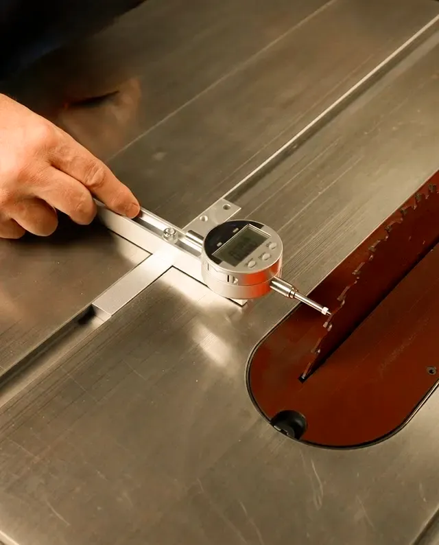
The baseline measurement evaluates the tool exactly as it cuts wood. This requires a precision dial indicator mounted to a magnetic base or a miter slot jig.
- Unplug the saw. Wait for the blade to stop completely and remove any throat plate only if your saw manual allows safe access.
- Raise the blade to its maximum height.
- Position the dial indicator so the plunger tip rests firmly against the flat plate of the blade, just below the carbide teeth. Do not measure on the carbide teeth themselves, as brazing thickness can vary and skew the reading.
- Mark the blade plate with a marker where the plunger touches.
- Zero the dial indicator.
- Slowly rotate the blade by hand, observing the dial. Keep the indicator on the same marked plate path and avoid sliding the tip across tooth gullets, printed labels, or carbide shoulders.
- Record the maximum positive and negative deflection. This number represents the total runout at the cut line.
For general woodworking on jobsite saws or contractor saws, total indicated runout near the blade edge in the 0.005–0.010 inch range may still produce usable cuts, depending on blade quality, feed rate, and cut type. For glue-line ripping, fine joinery, or premium cabinet saw work, lower numbers are preferable.
If the total runout exceeds acceptable limits, the next step is isolating the cause.
Step 2: The 180-Degree Isolation Test
If a saw shows significant runout at the blade edge, you must separate blade warp from arbor deflection. Machinists and experienced woodworkers use a simple elimination protocol known as the 180-degree test.
- Using the setup from Step 1, rotate the blade until the dial indicator reads the absolute highest point of runout (the peak wobble toward the indicator).
- Use a marker to draw a line on the blade exactly where the indicator tip is touching. Also, place a small mark on the end of the threaded arbor shaft to note its current position.
- Carefully loosen the arbor nut.
- Rotate the blade exactly 180 degrees on the arbor shaft. Keep the arbor shaft perfectly still.
- Tighten the arbor nut back down.
- Run the dial indicator against the blade again.
Interpreting the results: After rotating the blade 180 degrees while keeping the arbor position fixed, measure again. If the high spot follows the mark on the blade, the blade plate is the likely source. If the high spot stays tied to the same arbor position instead of following the blade mark, the source is likely in the arbor flange, washer, shaft, or bearing assembly.
Step 3: Measuring the Arbor Flange
When the 180-degree test points to the machine, you must measure the arbor assembly directly.
- Remove the blade and the outer washer. Clean the fixed arbor flange thoroughly with a synthetic scouring pad or mineral spirits. A single piece of compressed sawdust, pitch, or raised burr on the flange can create measurable runout at the blade edge.
- Position the dial indicator so the plunger rests against the machined blade-seat face of the inner, fixed arbor flange, as close to the outer edge of the flange as practical. Do not measure against a rough stamped edge or the threaded portion of the arbor.
- Keep indicator pressure light and consistent; excessive plunger force or uneven hand pressure can create misleading readings.
- Slowly rotate the arbor by turning the motor pulley or the belts by hand.
Acceptable Flange Tolerances: Because of the multiplication effect discussed earlier, flange tolerances must be tight. As a reference point, premium cabinet saw documentation may specify arbor runout around 0.001 inch maximum, and tuning references often describe less than 0.001 inch flange runout as a high-quality target. Budget jobsite saws may not consistently meet that level, so the number should be interpreted relative to saw class and intended work.
Step 4: Checking Bearing Play
If the flange measurement is erratic or changes depending on how you turn the shaft, the issue is likely the arbor bearings rather than a bent shaft.
With the dial indicator resting against the smooth side of the arbor shaft (not the threaded portion), apply moderate hand pressure laterally and vertically. The goal is to detect bearing play, not to flex the assembly. If the dial indicator registers movement when you apply pressure, the arbor bearings have play.
Mechanical slop in the bearings allows the entire shaft to float during a cut, producing unpredictable kerf widths and heavy vibration that no amount of upgrading will fix.
Understanding these mechanisms allows you to diagnose poor cut quality systematically. By moving from the blade edge inward to the flange, and finally to the bearings, you can determine exactly where the tool’s mechanical limits lie.